ANAND CLASSES Study Material and Notes to learn the fundamentals of electric circuits, including types of circuits, components, Ohm’s Law, and safety devices. Perfect for Class 10, JEE, and NEET foundation students with worksheets, MCQs, and revision notes.
🔌 Explain Electric Circuits
Q1: What is required for electrons to move and electric current to flow in a circuit?
Answer:
To make electrons move and generate an electric current, a source of electrical energy, like a cell or a battery, is essential. This source creates a potential difference (voltage) between its two terminals—positive (+) and negative (–). However, for electrons to flow, they need a conducting path, such as metal wires, which allows the charge to move from one terminal to the other. This movement of electrons constitutes the electric current.

🔍 Analogy: Just like water needs a pipe to flow from one place to another, electric current needs a conducting wire to flow from the negative to the positive terminal.
Q2: What is an electric circuit?
Answer:
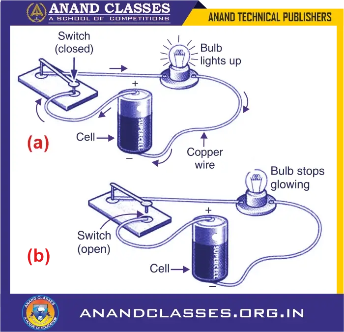
An electric circuit is a complete, closed loop through which electric current flows (above Figure). It includes:
- A power source (like a cell or battery)
- Conducting wires
- Load (like a bulb, fan, or resistor)
- A switch to open or close the circuit
If the loop is broken (open), current cannot flow. If it’s complete (closed), the electric current moves continuously.
💡 Example: A torch is an example of a simple electric circuit. When you press the switch, it completes the circuit and the bulb lights up.
Q3: How is a bulb connected in a simple electric circuit?
Answer:
In a basic circuit:
- The positive terminal of the cell is connected to one end of the bulb holder using a copper wire
- A switch is placed in between to control the flow of current
- The negative terminal of the cell is connected to the other end of the bulb
This forms a loop. If the switch is closed, current flows and the bulb glows.
Q4: What happens when the switch in the circuit is closed?
Answer:
When the switch is closed:
- The circuit becomes complete (unbroken)
- Electrons begin to flow from the negative terminal to the positive terminal through the external circuit
- The current flows through the bulb, and it starts glowing
💡 Concept Tip: A closed switch allows a continuous path for the charges to move.
Q5: What happens when the switch is opened?
Answer:
When the switch is open:
- A air gap (an insulating medium) is introduced in the circuit
- This interrupts the continuous path, so current cannot flow
- The bulb does not light up because the circuit is broken
🔌 Think of it like disconnecting a pipe—water stops flowing!
⚙️ Circuit Symbols – Explained
Q6: Why do we use symbols for electrical components in circuit diagrams?
Answer:
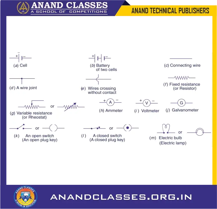
Drawing realistic pictures of electrical devices in every diagram is time-consuming and impractical. So, scientists have created universal symbols for each electrical component—called circuit symbols—that are easy to draw and understand globally.

🧠 Why it’s important: Helps electricians, engineers, and students understand circuits at a glance.
Q7: What does the symbol for a single cell look like and what do the lines represent?
Answer:
The symbol consists of:
- A long thin vertical line = positive terminal (+)
- A short thick vertical line = negative terminal (–)
This visual representation helps easily identify which side is positive and negative while drawing circuits.
Q8: What is a battery and how is it symbolized in a circuit?
Answer:
A battery is made by connecting two or more cells in series. In symbols:
- Multiple sets of long-short vertical lines are drawn
- The negative terminal of one cell is connected to the positive terminal of the next
🔋 More cells = Higher voltage = More power for bigger devices
Q9: What is variable resistance and how is it represented?
Answer:
Variable resistance (or rheostat) is a component that allows the resistance in a circuit to be changed. It’s shown by symbols that include an arrow over a resistor.
There are two main symbols used in diagrams.
Q10: What is the function of a rheostat in a circuit?
Answer:
A rheostat is used to regulate the flow of current by varying resistance, without changing the voltage.
- Increasing resistance = less current
- Decreasing resistance = more current
🎚️ Used in dimmer switches and fan regulators!
Q11: What is a galvanometer?
Answer:
A galvanometer is an instrument used to detect the presence and direction of current in a circuit. It is very sensitive, meaning it can detect even small currents.
📍 You’ll study it more deeply in higher classes when learning about magnetic effects of current.
Q12: What is the role of a switch in an electric circuit?
Answer:
A switch (or plug key) controls the completion or interruption of a circuit:
- Closed switch = circuit complete → current flows
- Open switch = circuit broken → no current flows
🛠️ Acts like a gate for electric flow!
🔁 Circuit Diagrams – Visual Representation
Q13: What is a circuit diagram?
Answer:
A circuit diagram is a simplified drawing using symbols to show how components are connected in a circuit. It helps visualize the arrangement and working of a circuit without physical models.

🧾 Used extensively in designing real-life electronics.
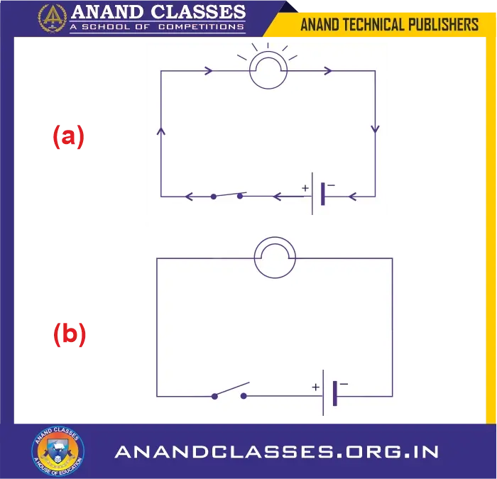
Q14: How is the circuit in Figure represented in a circuit diagram?
Answer:
The closed circuit with:
- A cell,
- A bulb, and
- A closed switch
…is shown using symbols in Figure. This represents a working circuit where current flows and the bulb glows.
Q15: What happens in the circuit represented by Figure ?
Answer:
The switch is closed, so:
- The circuit is complete
- Electrons flow continuously
- The bulb lights up
This shows a functioning circuit with no gaps.
Q16: How is the circuit in Figure represented in a circuit diagram?
Answer:
In Figure, the same components (cell, bulb, switch) are shown, but the switch is open—indicating a gap in the circuit. Hence, it’s a non-functional circuit.
Q17: What happens in the circuit represented by Figure?
Answer:
- The open switch breaks the circuit
- No current flows
- The bulb does not glow
⚠️ A break in the path stops the electron flow, just like a break in a pipeline stops water.
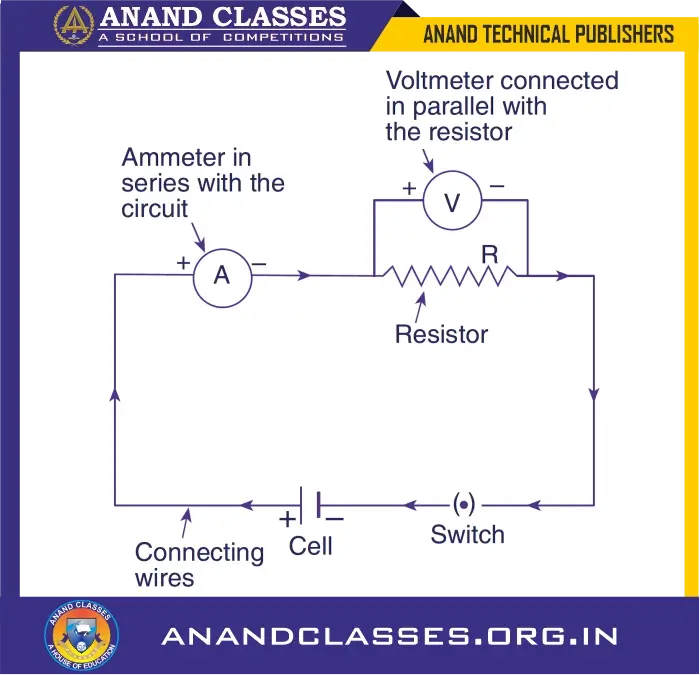
Q18: Describe the components and connections in the electric circuit shown in Figure.

of a cell, a resistor, an ammeter, a
voltmeter and a switch (or plug key).
This is a more advanced circuit. It includes:
- A resistor R connected to a cell via a switch
- An ammeter A connected in series with R to measure current
- A voltmeter V connected in parallel with R to measure potential difference (voltage)
📊 This is the standard method of measuring current and voltage in electric circuits.
🔍 Multiple Choice Questions (MCQs) with Explanations
- Which of the following is a correct statement about a closed electric circuit?
A. Current flows from negative to positive terminal
B. No current flows at all
C. Current flows from positive to negative terminal
D. Bulb will never glow ✅ Answer: C
🔍 Explanation: In a closed circuit, current flows from the positive terminal of the battery through the circuit to the negative terminal. - In an electric circuit, a fuse is connected in:
A. Parallel to the circuit
B. Series with the circuit
C. Either series or parallel
D. None of these ✅ Answer: B
🔍 Explanation: A fuse is connected in series so that it can break the circuit in case of excessive current flow. - Which component is used to measure electric current?
A. Voltmeter
B. Ammeter
C. Rheostat
D. Resistor ✅ Answer: B
🔍 Explanation: An ammeter is always connected in series and measures the flow of current. - A voltmeter is always connected in:
A. Series with the device
B. Parallel with the device
C. Either way
D. None of these ✅ Answer: B
🔍 Explanation: A voltmeter measures potential difference and is connected in parallel to the component. - Which of the following symbols represents a cell in a circuit diagram?
A.–|–
B.–(–
C.+|–
D.|–|✅ Answer: C
🔍 Explanation: The longer line represents the positive terminal and the shorter line represents the negative terminal of a cell. - What happens if a wire with zero resistance is connected across the terminals of a cell?
A. Normal current flows
B. No current flows
C. Short circuit occurs
D. Bulb glows more brightly ✅ Answer: C
🔍 Explanation: A wire with zero resistance causes a short circuit, leading to excessive current that can damage the battery or circuit. - Which of the following remains the same in all components connected in series?
A. Voltage
B. Current
C. Resistance
D. Power ✅ Answer: B
🔍 Explanation: In a series connection, the same current flows through all components. - When resistors are connected in parallel, the total resistance:
A. Increases
B. Decreases
C. Remains unchanged
D. Becomes zero ✅ Answer: B
🔍 Explanation: In a parallel combination, the equivalent resistance is less than the smallest individual resistance. - In a circuit with two identical bulbs in series, if one bulb fuses:
A. Both bulbs glow
B. Only one bulb glows
C. Circuit breaks, both stop glowing
D. Bulb glows more brightly ✅ Answer: C
🔍 Explanation: In a series circuit, failure of one component breaks the entire circuit. - Which of the following statements about a resistor is true?
A. It stores charge
B. It produces current
C. It resists current
D. It measures voltage ✅ Answer: C
🔍 Explanation: A resistor is a component that opposes the flow of current.
🧠 Assertion-Reason Type Questions
Question 1:
Assertion (A): A voltmeter is connected in parallel across a component.
Reason (R): A voltmeter has very high resistance.
- A. Both A and R are true, and R is the correct explanation of A.
- B. Both A and R are true, but R is not the correct explanation of A.
- C. A is true but R is false.
- D. A is false but R is true.
✅ Answer: A
🔍 Explanation: A voltmeter is connected in parallel and has high resistance to ensure it doesn’t alter the current in the circuit.
Question 2:
Assertion (A): In a series circuit, the voltage is the same across all components.
Reason (R): In series, all components get the same amount of energy.
- A. Both A and R are true, and R is the correct explanation of A.
- B. Both A and R are true, but R is not the correct explanation of A.
- C. A is false but R is true.
- D. Both A and R are false.
✅ Answer: C
🔍 Explanation: In a series circuit, current remains the same, but voltage gets divided. So assertion is false, but reason is true in a general context.
Question 3:
Assertion (A): A fuse should have a low melting point.
Reason (R): So that it melts when excessive current flows.
- A. Both A and R are true, and R is the correct explanation of A.
- B. Both A and R are true, but R is not the correct explanation of A.
- C. A is true but R is false.
- D. Both A and R are false.
✅ Answer: A
🔍 Explanation: The purpose of a fuse is to melt and break the circuit when current exceeds a safe limit, preventing damage.
Question 4:
Assertion (A): An ammeter is connected in parallel.
Reason (R): It has very high resistance.
- A. Both A and R are true, and R is the correct explanation of A.
- B. Both A and R are true, but R is not the correct explanation of A.
- C. A is false but R is true.
- D. Both A and R are false.
✅ Answer: D
🔍 Explanation: An ammeter is connected in series and has very low resistance to avoid changing the current it measures.
💡 Do You Know?
- A switch in an electric circuit acts like a gate that opens or closes the circuit.
- A fuse is made of a metal with a low melting point so that it melts quickly if the current exceeds a safe limit.
- Ohm’s Law is the foundation of all electric circuit analysis: V=IRV = IR
- The direction of conventional current is from the positive terminal to the negative terminal, though electrons actually flow in the opposite direction.
- Short circuiting occurs when the resistance in the circuit drops to near zero, allowing excessive current that can cause damage or fire.
📝 Worksheet: Electric Circuits
Fill in the Blanks:
- Electric current is measured in _______.
- A ________ is used to open or close a circuit.
- A device that protects a circuit from overcurrent is called a _______.
- Current always flows in a _______ circuit.
Answer in One Word:
- Name the instrument used to measure voltage.
- What is the SI unit of resistance?
- What material is used for fuse wire?
Circuit Diagram Practice:
- Draw a simple circuit using a cell, switch, resistor, and bulb.
- Label each component properly.
🧪 Test Paper – Electric Circuits
Total Marks: 20
Time: 30 minutes
Section A: MCQs (1 × 5 = 5 marks)
Choose the correct option for each:
- The flow of electric current is due to movement of:
A. Neutrons
B. Protons
C. Electrons
D. Ions - Which device is used to change resistance in a circuit?
A. Resistor
B. Rheostat
C. Fuse
D. Switch - A complete path for current flow is called a:
A. Loop
B. Circuit
C. Resistance
D. Wire - In circuit diagrams, wires are shown as:
A. Dotted lines
B. Curved lines
C. Straight lines
D. Zigzag lines - A short circuit occurs when:
A. Resistance is very high
B. Fuse is removed
C. Resistance is nearly zero
D. Voltage is zero
Section B: Short Answer Questions (2 × 3 = 6 marks)
- Differentiate between open circuit and closed circuit.
- Draw a labeled diagram of a simple circuit including battery, resistor, and switch.
- Why are fuses essential in household wiring?
Section C: Long Answer Question (1 × 4 = 4 marks)
- Explain the function of a switch, fuse, and circuit breaker in an electric circuit.
Section D: Application-Based Question (1 × 5 = 5 marks)
- You are given a battery, bulb, switch, and connecting wires. Describe how you will set up a working circuit. Also explain what happens if:
- The switch is open
- A fuse is inserted
- A voltmeter is connected across the bulb
⚡ Important Points for Quick Revision
- Electric Circuit: A closed loop allowing current to flow.
- Current (I): Flow of charges, measured in amperes (A).
- Voltage (V): Potential difference, measured in volts (V).
- Resistance (R): Opposition to current, measured in ohms (Ω).
- Ohm’s Law: V = IR
- Series Circuit: Components connected end-to-end; same current flows through all.
- Parallel Circuit: Components connected across the same voltage.
- Ammeter: Measures current; connected in series.
- Voltmeter: Measures voltage; connected in parallel.
- Fuse: Safety device that melts when current exceeds safe limit.
- Switch: Controls the flow of current.


